Ask AI for a summary
A product photo helps buyers recognize a machine. It rarely shows how the parts fit together. MiniMax H3 Image can bridge that gap with a concept exploded view, an explanatory cutaway, or a sheet of product views. The image can make a sales conversation easier, but a convincing drawing can also show a seal, fastener, or flow path that the actual product does not have. MiniMax H3 Image produces pixels, not verified CAD or a maintenance drawing. For a diagram about a real model, give it that model's parts evidence, then check every visible claim before publication.
Key takeaways
- Use the product photo for visible appearance and a matching parts source for hidden structure.
- Choose an exploded view, cutaway, or multi-view sheet according to the reader's question.
- Check component count, assembly order, callouts, and source identity before publishing.
- A 4K file can improve legibility; it cannot certify mechanical accuracy.
What MiniMax H3 Image Can Make for Industrial Products
An exploded view separates components along their assembly directions. It helps a buyer understand broad construction or helps a trainer point to a replaceable assembly. A cutaway exposes an internal path, such as fluid moving through a pump. A multi-view sheet keeps the outside of a product visible from several sides, which helps a customer identify ports, controls, and mounting orientation.
The MiniMax H3 Image documentation describes a still-image generation and editing model that accepts up to 16 references and offers 1K, 2K, and 4K output areas. The same model supports a written prompt or image editing. MiniMax H3 video is a separate route, even though the names are similar. The official specifications describe image size and input limits, not verified engineering precision (MiniMax model documentation, November 2026).
| Visual | Reader's question | Minimum evidence | Main risk |
|---|---|---|---|
| Exploded view | What assemblies sit between the two ends? | Product photo plus a matching parts drawing or bill of materials (BOM) | Invented parts or false assembly order |
| Cutaway | Where does material or fluid travel? | Product photo plus a matching section drawing | A plausible but false internal path |
| Multi-view sheet | Which side has the shaft, ports, or terminal box? | Real photographs from the required views | Inconsistent exterior details or implied dimensions |
Choose the illustration type before writing the prompt. An attractive cutaway cannot answer a question about the number of serviceable parts. A multi-view sheet can show orientation without implying that the model knows what is inside.
MiniMax's published industrial showcase includes an exploded concept motorcycle with its prompt and output. It shows that the model can arrange separated elements and labels. It is a vendor demonstration of a concept vehicle, so it does not establish that an arbitrary production assembly has been reconstructed correctly. The output also contains visibly malformed callouts, a reason to inspect text even in an official example.
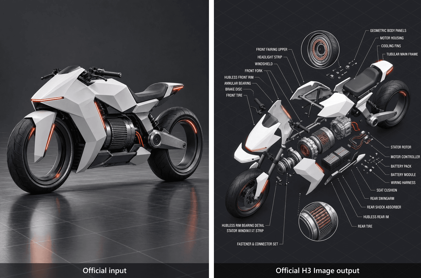
The official prompt specifies the concept motorcycle and asks for an exploded layout. This input-to-output pair shows layout control, not proof of a real product's internals.
Start with a Product Photo and a Parts Source
Consider a 3-piece stainless-steel ball valve for a catalog page. A whole-product photo can constrain the handle, exterior proportions, surface finish, end connections, and viewpoint. It cannot tell an editor how many seats sit beside the ball, what stem packing the manufacturer used, or which fasteners hold the body together. Those facts must come from documentation for the same manufacturer, model, size, and revision.
Build a small input record before opening the image editor:
- Record the exact model, size, connection type, revision, source links, and image-use rights.
- Save an authorized whole-product photo as Picture 1.
- Save the matching exploded drawing and BOM as Picture 2. If the drawing covers several variants, mark the relevant column before prompting.
- Transcribe the part names, quantities, and assembly sequence you expect to see. Keep that list outside the generated image for review.
A 3-piece valve is useful precisely because its outer form does not reveal all the seals and hardware. In one published manufacturer parts sheet, a ball has a quantity of 1, seats have a quantity of 2, and end pieces have a quantity of 2 for the stated size range. The same sheet shows handle variants and size-dependent hardware. Applying the wrong size note could make an otherwise coherent picture false. Treat this sheet as an example of the evidence required, not as a BOM for a different valve (36 Series product and parts sheet).
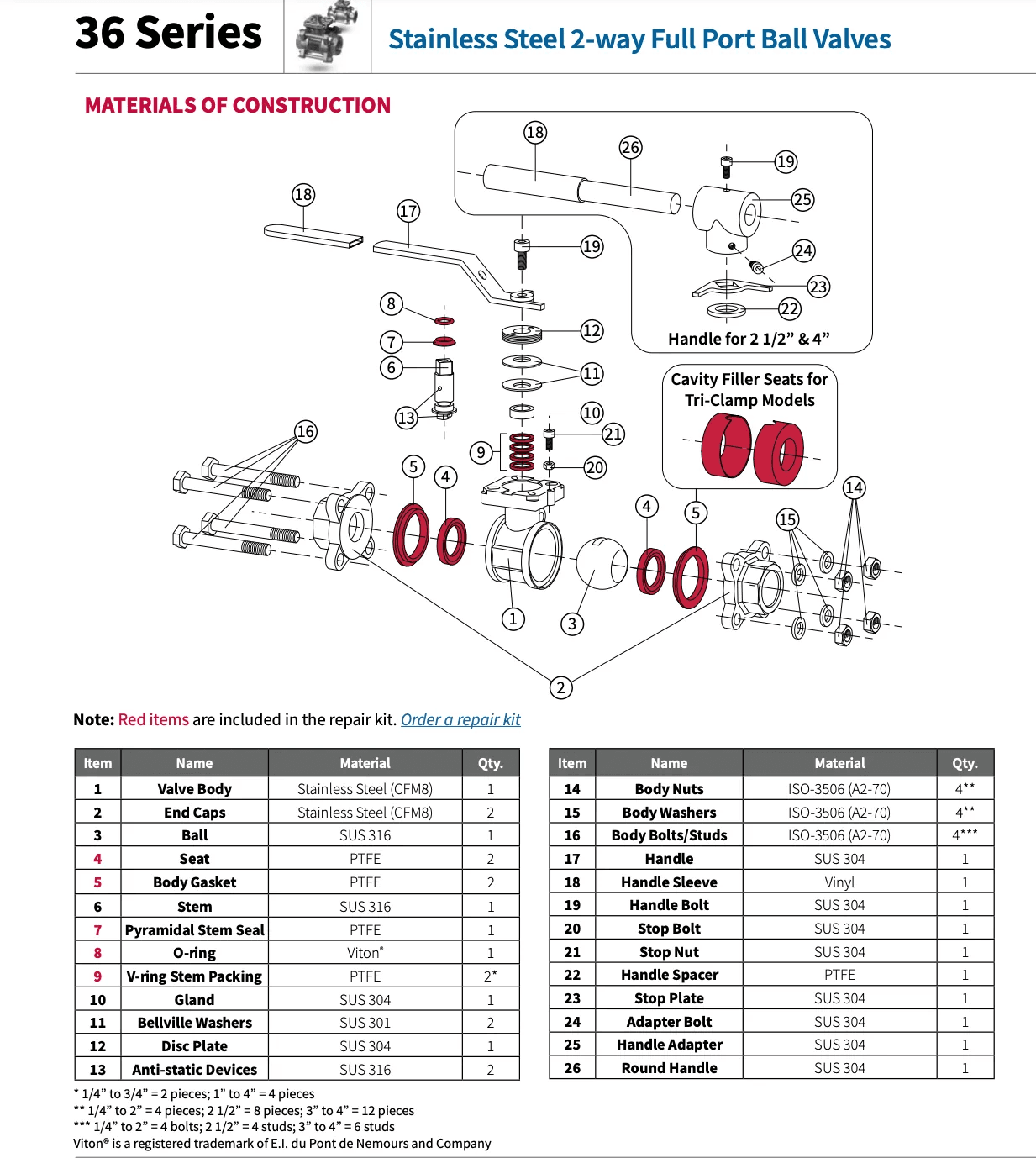
The 36 Series parts sheet pairs numbered components with quantities and size-dependent hardware notes. A reviewer must select the correct variant before using it to check an image.
If a photo and a parts source demonstrably refer to the same product, develop a candidate product diagram. If you only have the photo, publish an image solely as a clearly labeled concept illustration. A generic valve schematic cannot verify the hidden parts of a specific valve.
Make an Exploded View with MiniMax H3 Image
Open the MiniMax H3 Image editing workflow in MiniMax Design and upload the photo first and the matching parts source second. Confirm the visible upload order. In the prompt, assign the sources separate jobs: Picture 1 fixes the exterior; Picture 2 defines components, quantities, and assembly order. The prompt below is a template for a real pair of matching inputs. The supplied candidate shown after it has not been verified as a MiniMax H3 Image result or as a diagram of the cited valve.
Ask for spacing and assembly axes before styling. The reviewer needs to see which part belongs to which opening, and a label needs room to point to one object. A neutral background and even light help that inspection. Styling words such as "professional" cannot supply missing mechanical evidence.
plaintext1Create an explanatory exploded-view diagram of the exact three-piece stainless-steel ball valve shown in <Picture 1>. Use <Picture 1> for the product's external shape, handle, surface finish, proportions, and camera angle. Use <Picture 2> only as the source of truth for component names, component count, and assembly order. 2 3Arrange the verified components along the valve's real assembly axes in a clean, slightly elevated isometric view. Keep each component separated enough to see its relationship to the next one. Preserve the shape of the center body and both end pieces. Include only parts that can be identified in <Picture 2>; do not invent hidden seals, fasteners, ports, or measurements. 4 5Use a neutral light background and even technical lighting. Leave clear space around the diagram for labels. Add short numbered callouts only for components whose names and numbers are legible in <Picture 2>. If a label cannot be read with confidence, leave that callout blank. Do not add dimensions, tolerances, material grades, safety claims, or certification marks. Output a single flat diagram, not a poster mockup.
Generate 1 PNG at 2K for the layout review. Preserve the prompt, references, settings, and file version with the draft. Once the component layout passes review, a 4K output can help with small text and print placement. MiniMax lists 1 to 10 images per request; requesting 1 keeps the review trail clear. Check the interface's current controls before each run, since a product UI can differ from a model specification.
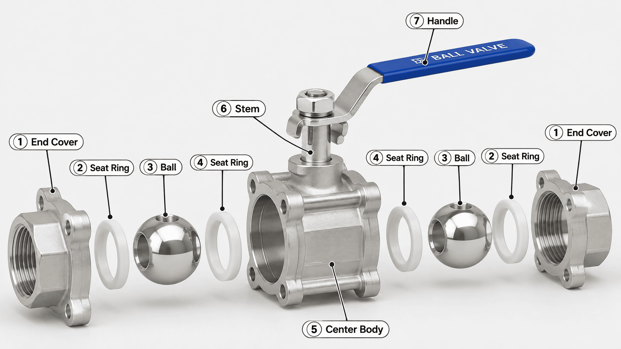
This supplied candidate is a review example, not an approved product diagram or a verified MiniMax H3 Image test. It shows two balls and repeats part numbers across different objects. The cited 36 Series parts sheet lists one ball for its stated variant. Check the exact model and BOM before using any generated diagram as product evidence.
Begin the first review with the valve's large relationships: ball within the center body, stem above it, seats on the appropriate sides, and end pieces along the assembly axis. Compare each visible item with the correct BOM column. If the picture contains an extra washer or merges two seats into one, mark the candidate as failed regardless of how polished it looks.
Adapt the Method to Cutaways and Multi-View Sheets
A cutaway answers a different question from an exploded view. For a centrifugal pump, a sales or training graphic may need to show where liquid enters, how the impeller redirects it into the volute, and where it leaves. Use an exterior reference to preserve the visible casing and port positions. Use a section drawing for the internal path and impeller placement. Without that second source, a clean arrow can still point through the wrong chamber.
For a real product, upload a photo of the exact pump as Picture 1 and its matching section drawing as Picture 2. The comparison below uses an exterior illustration and a single-impeller section from the same Grundfos NS-series manual; that series-level pair does not establish a particular model and revision. Use this cutaway prompt when you have a verified pair:
plaintext1Create one cutaway explanatory diagram of the exact centrifugal pump in <Picture 1>. Use <Picture 1> to preserve the visible casing, inlet and outlet positions, connection shapes, and exterior viewpoint. Use the matching section drawing in <Picture 2> as the only source for the impeller, volute, internal passage, and flow direction. 2 3Expose only the section needed to show liquid entering the inlet, moving through the impeller and volute, and leaving the outlet. Show one continuous flow path with a few clear arrows, each following the passage in <Picture 2>. Keep the visible housing and port positions consistent with <Picture 1>. Omit bearings, seals, cavities, and other hidden parts unless <Picture 2> clearly identifies them. Do not add dimensions, performance numbers, or unverified labels. Output one flat technical diagram on a neutral light background.
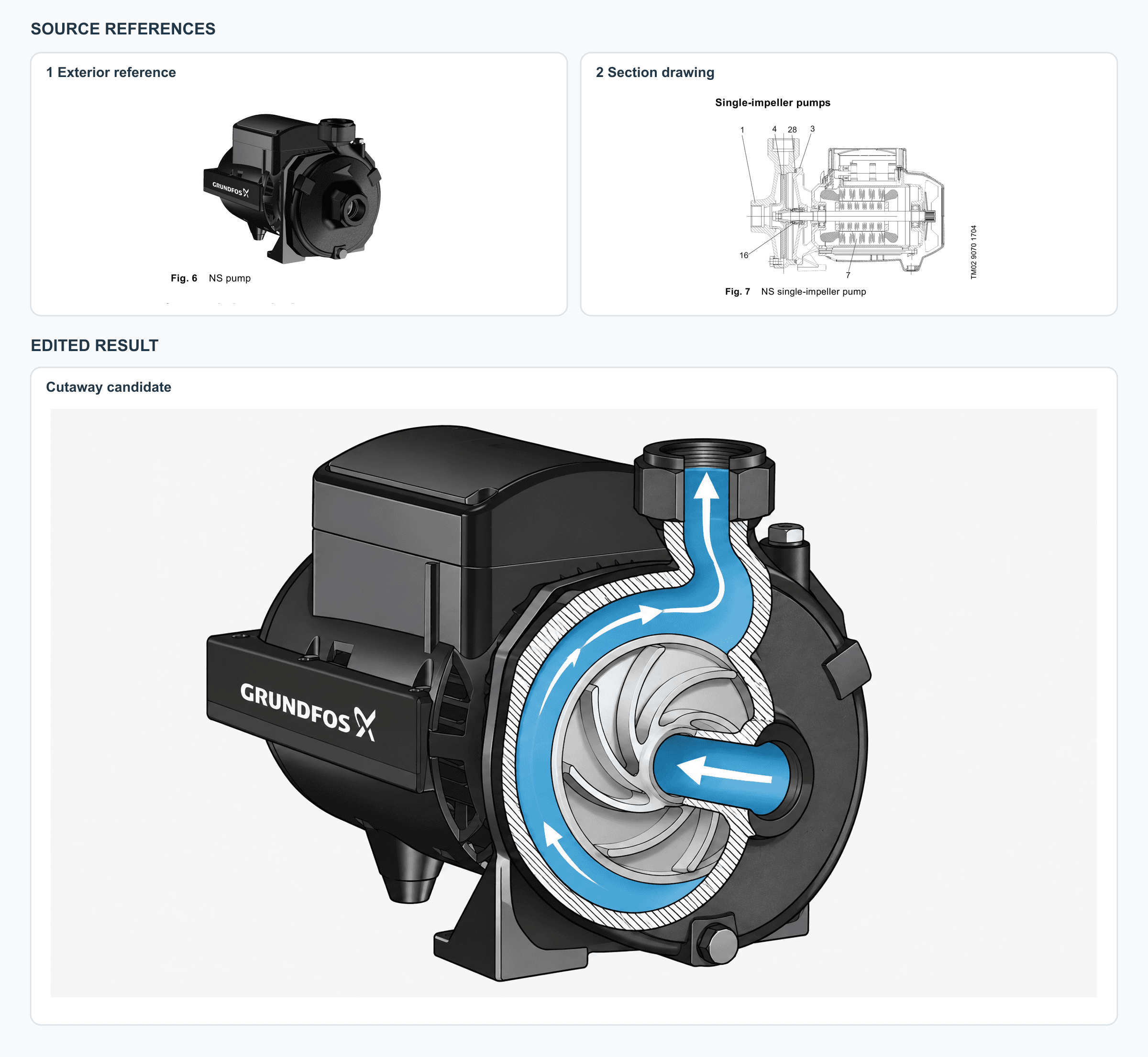
Top: the NS-series exterior illustration and single-impeller section from the Grundfos product manual. Bottom: the supplied cutaway candidate. The arrows are useful for explaining a possible flow path, but the exact model and each arrow still need to be checked against a matching section drawing before publication.
Before publishing, trace each arrow against the section drawing. Leave bearings and seal stacks out unless the matching source identifies them.
An electric motor sheet serves a buyer who needs to check its outside orientation. Supply front, side, and rear references of the same motor and request three aligned views. The output should preserve the visible shaft, terminal box, ventilation openings, mounting feet, and housing shape. A three-view image can help a salesperson discuss which face is which. It cannot establish mounting-hole dimensions or electrical ratings.
Upload views of the same motor as Picture 1 (front), Picture 2 (side), and Picture 3 (rear). Align the product orientation as closely as the sources allow. The comparison below uses three views from one ABB M3LP 355 drawing rather than photographs. Use this multi-view prompt:
plaintext1Create one three-view exterior reference sheet of the same electric motor shown in <Picture 1>, <Picture 2>, and <Picture 3>. Arrange three aligned columns in this order: front view from <Picture 1>, side view from <Picture 2>, and rear view from <Picture 3>. Keep the apparent scale, housing proportions, finish, and lighting consistent across all three columns. 2 3Preserve only exterior features visible in the references: the shaft and its shape, terminal box location, ventilation openings, mounting feet, and housing outline. Keep repeated details on the same physical side of the motor in every view. Do not invent a fourth view, internal components, mounting-hole dimensions, electrical ratings, or certification marks. If a detail is obscured in its source reference, leave it obscured rather than guessing. Output one flat three-view sheet on a neutral light background with clear spacing between views.
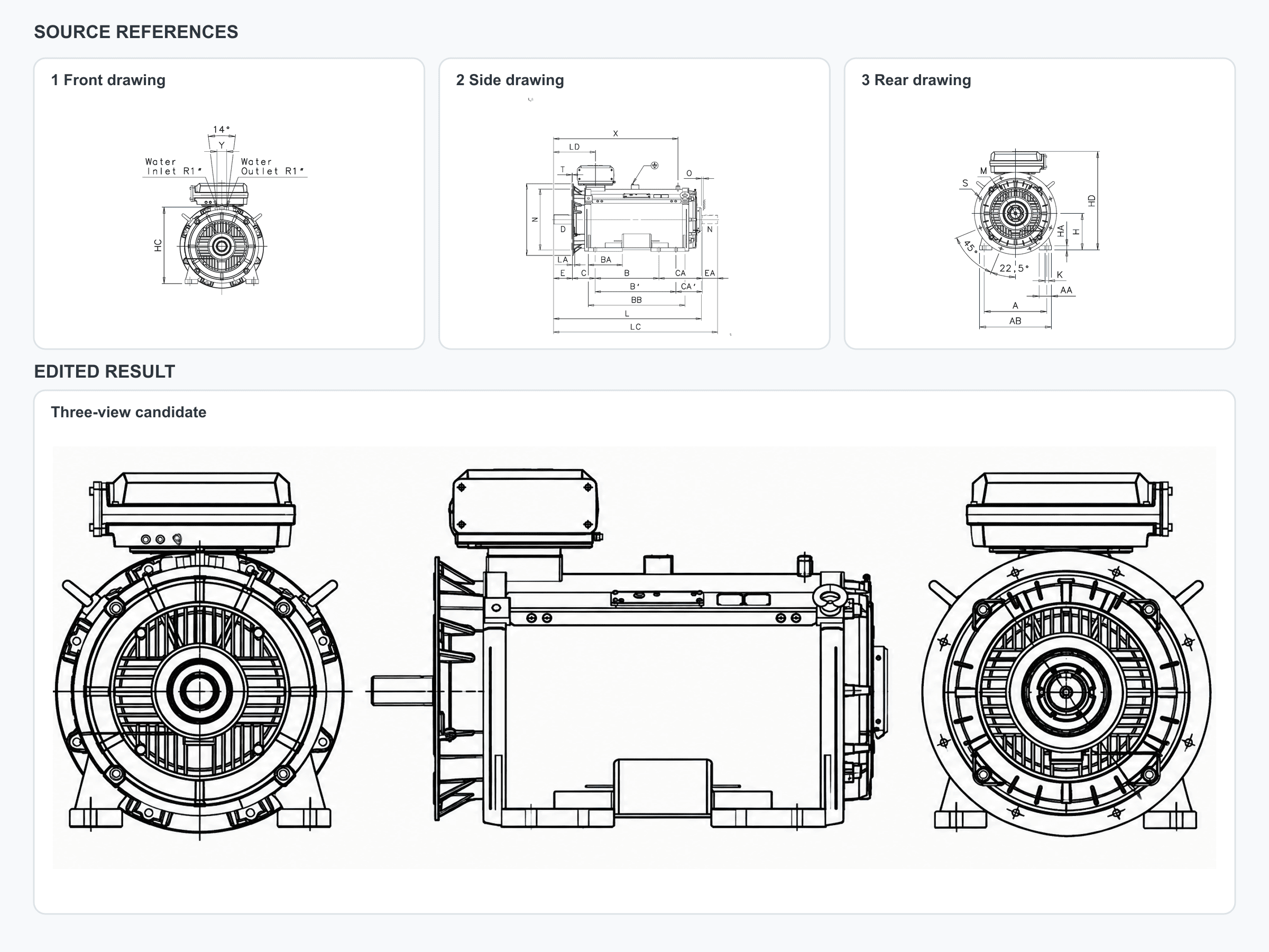
Top: front, side, and rear drawings for the ABB M3LP 355 foot-and-flange-mounted motor from the ABB catalog. Bottom: the supplied three-view candidate with dimensions omitted. Check the shaft, terminal box, feet, and repeated details against the source; use the manufacturer drawing for dimensions.
Review repeated details between views: the terminal box cannot jump to the opposite side, and the shaft should not change shape. Leave dimensions to a manufacturer drawing or CAD export. In both examples, the reference set determines what the picture may claim; the prompt mainly controls its presentation.
Check Every Part Before You Publish
A community test turned one espresso-machine photo into a detailed MiniMax H3 Image exploded composition with labeled internals. The author explicitly framed the result as a visual concept, and a reader asked to see the machine's actual internals. That exchange captures the publishing problem: a complete-looking image can persuade before anyone has checked the hidden parts (community espresso-machine test, November 2026).
The official motorcycle output offers a visible audit example: its lower callouts include a truncated rear-rim label and a garbled stator label. A reviewer can catch those errors before debating whether the depicted parts are real.
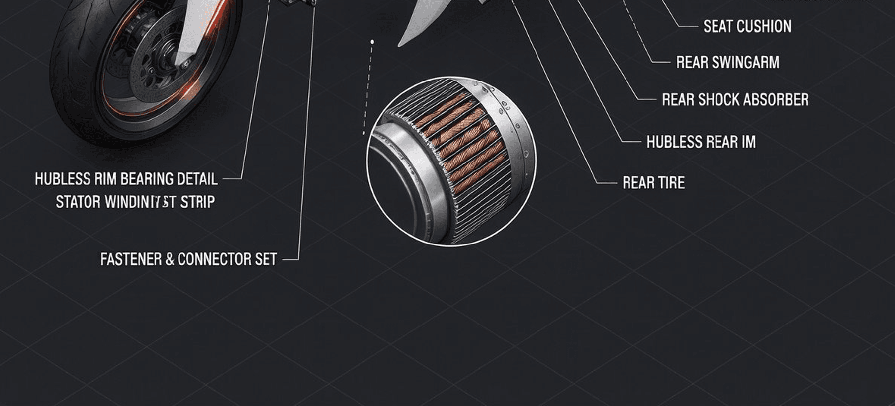
The cropped official output shows the actual callout errors. It is a label-review example, not a claim about the real construction of the concept motorcycle.
Use an audit table on the actual product candidate, not a general impression of image quality. Give the reviewer the source photo, the correct model's BOM and drawings, and the candidate image side by side. For every disagreement, write the source item number and exact correction required.
| Check | Compare against | If it fails |
|---|---|---|
| Model and variant | Product record, nameplate, document revision | Stop; replace the mismatched reference |
| Exterior, port, handle | Authorized product photos | Correct the view or reject the candidate |
| Part name and quantity | Matching BOM, correct size column | Remove or correct the part and repeat the count |
| Assembly order and axis | Manufacturer exploded drawing | Regenerate from the drawing or use approved CAD |
| Leader line and label | BOM item number and name | Fix the callout; leave uncertain names blank |
| Flow arrow or section | Matching section drawing | Remove the unsupported path |
| Units and claims | Approved technical copy | Delete anything absent from the source |
| Source trace and sign-off | Saved files and reviewer record | Hold publication until complete |
The release label should match the evidence. A concept visual may show a possible arrangement if its caption says so and does not name invented parts as facts. A reviewed marketing diagram requires a matched source set, completed checks, and the relevant product or engineering owner's approval. Engineering documentation belongs to a controlled CAD and drawing process with dimensions, revision control, and technical sign-off. An AI image does not become that third category because it has fine lines or 4K pixels.
For higher-risk uses such as installation, maintenance, or safety instructions, give the candidate to the responsible engineer and use the approved drawing if the generated geometry cannot be reconciled. A marketing review does not replace a service-document review.
Fix Labels and Geometry Without Rebuilding the Whole Diagram
Correct the evidence first. A vague source image, the wrong variant, or a misread BOM quantity will keep causing trouble across prompt revisions. After fixing the input, make one explicit change per iteration and compare the new file with the previous version. Save both versions so an improved label does not hide a newly moved component.
Use this revision prompt after checking the actual upload order. Put the generated candidate first, followed by the original photo and matching parts source:
plaintext1Edit <Picture 1> only to correct the following verified issue: [paste one specific issue and its correct value from the matching parts source]. Use the original product photo and the matching parts source supplied after <Picture 1> to check the correction. Keep every other component's shape, count, position, viewpoint, background, and callout number unchanged. Remove any label that cannot be verified. Do not introduce new parts.
When labels overlap or point to the wrong item, ask the model for numbered callouts only. Then place the approved part names in a vector editor from the BOM. That gives the editor control over spelling and leader lines. Recheck the final composite, since a manual callout can be wrong too.
A missing seal or impossible assembly axis needs source evidence, not stronger adjectives. Supply the correct drawing, simplify the diagram to confirmed assemblies, or remove the cutaway. Ask whether a named reviewer can trace every visible claim to a document.
Where to Run It, What It Costs, and What the License Changes
MiniMax H3 Image is available through MiniMax Design, with model details in the MiniMax documentation. As of November 2026, the Atlas Cloud catalog and endpoint index available for this review did not show a verifiable static MiniMax H3 Image model page. The similarly named Atlas Cloud MiniMax H3 video entries describe video generation. Use MiniMax Design for the MiniMax H3 Image procedure above.
If your team already works with Atlas Cloud and wants another reference-image editing route for the same product materials, GPT Image 2.6 Sunburst Edit on Atlas Cloud is an alternative workflow. Its page lists up to 16 reference images, a max quality option, high complexity, PNG output, and sizes up to 3840 by 2160. Upload the product photo and matching parts source, then rewrite "Picture 1" and "Picture 2" as "first uploaded image" and "second uploaded image." Use 1 output and inspect the actual controls before running. Label an Atlas Cloud output as a GPT Image 2.6 Sunburst Edit result, never as a MiniMax H3 Image test.
The Atlas Cloud model catalog lists current pricing for GPT Image 2.6 Sunburst Edit. Check the playground's price for your selected size and quality before generating; settings and discounts can affect the bill.
MiniMax's open-weight license also needs a deliberate check. Its published terms exclude the United States, European Union, United Kingdom, and South Korea from the applicable territory, and require prior written authorization above $1 million in annualized revenue or for a third-party hosted service. Have legal counsel review the exact deployment and publication path under the current license in the official repository. "Open weights" alone does not settle commercial rights for an overseas team.
For industrial product diagrams made with MiniMax H3 Image, the repeatable path is photo, matching parts evidence, tightly scoped prompt, generated candidate, and item-by-item review. If a product manager cannot identify the same model in both inputs, stop at a concept illustration. If engineering can trace each important part and label to a controlled source, the team can consider a reviewed marketing diagram. Keep the original CAD and manufacturer documentation as the source for any dimension, repair step, or safety claim.
Frequently Asked Questions
Can MiniMax H3 Image make an exploded diagram from one photo?
It can make a visual concept from one photo, as the community espresso-machine example illustrates. A photograph does not reveal every internal component, so supply a matched parts source before using the result to explain a real product's construction.
Does 4K make the diagram technically accurate?
No. A larger image may make small callouts easier to inspect. Accuracy depends on the reference evidence and on a reviewer checking counts, geometry, and labels.
Can a MiniMax H3 Image diagram replace CAD?
No. Use a controlled CAD export or approved engineering drawing when dimensions, tolerances, assembly instructions, or safety decisions matter. The image model is useful for explanatory concepts and reviewed communications.
Is MiniMax H3 Image the same as MiniMax H3 video?
No. MiniMax H3 Image generates and edits still images. MiniMax H3 video produces motion, and an Atlas Cloud MiniMax H3 video listing is not a MiniMax H3 Image editing endpoint.